Space Designer Communication format (SDCF for short) allows independent developers to create importers and exporters that can convert to or from any given BIM format (e.g. RVT, NWD, DWG, IFC etc). SDCF files are uncompressed JSON data files that can be imported directly into Space Designer as new projects. Space Designer itself uses JSON to store the information of the buildings created in it, but SDCF format does not exactly match Space Designer's inner logic. Some properties are explicitly expressed in SDCF that are calculated runtime in Space Designer, to make conversions easier. The output files are free from any dependencies to the Space Designer core source code or API and can be used independently.
These objects are the building blocks of the SDCF JSON file. Some of them match the Space Designer core JSON format exactly, some of them differ by a couple of attributes and there are some objects introduced only for the SDCF format. The naming conventions of SDCF follow buildingSMART's IFC (Industry Foundation Classes) specification where it’s possible.
PointModel
{
  "x": double,
  "y": double
}
PointModel is used to represent 2D points in the horizontal X-Y plane.
StoreyModel
{
  "uid": string,
  "name": string,
  "height": double
}
Storeys are “levels” in Space Designer. Each storey has a unique identifier, a name and the height of the level.
EntityModel
{
  "uid": string,
  "level": string
}
EntityModel is an abstract base for each SDCF-serializable entity in Space Designer. It can not be instantiated on its own, but it provides fields and methods that each entity will have. The uid is a unique identifier of given entity, and the level is the uid of the storey that will store the entity. In many industry standard BIM format, entities can spawn multiple storeys; this is unsupported in Space Designer at the moment, so each entity will have one and only one storey that it belongs to.
WallModel
{
  "type": "Wall",
  "uid": string,
  "level": string,
  "open": boolean,
  "divide": boolean,
  "wallType": string,
  "phase": string,
  "height": double,
  "thickness": double,
  "axis": {
	"position": double,
	"offsetLeft": double,
	"offsetRight": double
  },
  "polyline": PointModel[],
  "profile": PointModel[]
}
Wall materials are not exported at the moment.
The axis of the wall is represented by a polyline. For regular walls, this just has two points, the cornerLeft and the cornerRight point of the wall. The direction of the corners does not depend on the actual position and orientation of the corners, the original drawing direction matters only. (The first drawn corner will be the left, the second one will be the right corner, and the axis orientation will be calculated in the left to right direction.
Each wall has a closed 2D profile curve to represent the wall (calculated from the intersection points of the wall), height, thickness and axis information. Axis position has to be between 0 (outer axis) and the thickness (inner axis), the offsetLeft and offsetRight attributes have to sum up exactly to the wall’s thickness.
The "wallType" and "phase" parameters are strings chosen from a predefined list, they can hold additional user-defined information about the wall. These attributes alongside "open" and "divide" are exported directly from Space Designer's inner logic.
Curved walls are represented by wall segments in Space Designer, however this is under review and will be changed soon. The SDCF representation of curved walls has already been implemented to match the interface that will be applied in the future, so CurvedWalls are just WallModels in the output SDCF.
ItemModel
{
  "type": "Item",
  "uid": string,
  "level": string,
  "x": double,
  "y": double,
  "z": double,
  "width": double,
  "length": double,
  "height": double,
  "rotation": double,
  "catalog": string,
  "category": string,
  "categoryId": string,
  "instance": string,
  "instanceId": string,
  "voids": string,
  "openingType": OpeningType,
  "flipHorizontal"?: boolean,
  "flipVertical"?: boolean
}
Items are objects that can be construction elements (doors, windows, etc.) or decoration items (bathtubs, kitchen appliances, etc). Currently only those items are exported that cut a hole into a wall. The item’s bounding box position and dimensions are exported ([x, y, z] for position and [width, length, height] for dimension) as 3D vectors valid in SDCF space. (See below for further info on coordinate system transformations.)
Items can also have rotation, angles are in radians, measured in the positive direction along the vertical axis.
Item information and hierarchy in Space Designer is stored in a tree structure. Catalog > Category (and CategoryId) > Instance information is stored, e.g. exporting a simple door will result in the following:
  "catalog": "Construction",
  "category": "Doors",
  "categoryId": "1",
  "instance": "Wood Door",
  "instanceId": "2752",
There are four OpeningTypes that originate from IFC:
Each item can be connected to only one wall. If the given item voids a wall, the voids attribute stores the uid of given wall.
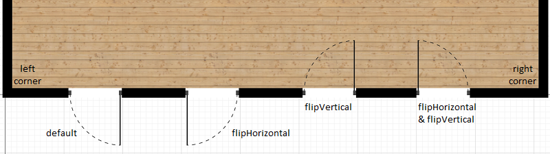
When the item is snapped on a wall, the default horizontal snapping direction follows the line drawn from the given wall's left corner to its right corner. The item's normal vector points to the left side of the wall. The models in Space Designer are designed to align the same way, so for example a door's swing direction and hinge side will always be determined by the direction of the wall. Items can be flipped both horizontally and vertically, so the default directions can be modified. When an item is flipped, flipHorizontal and/or flipVertical will be true, otherwise these attributes are unset.
BoundaryModel
{
  "type": "Boundary",
  "uid": string,
  "level": string,
  "label": string,
  "position": PointModel,
  "showFloor": boolean,
  "showCeiling": boolean,
  "ceilingThickness": double,
  "height": double,
  "profile": PointModel[],
  "holes": PointModel[][]
}
Rooms are defined by their boundaries in Space Designer. The thickness of the floor will always be zero, because Space Designer uses 2D representation for floors. The ceiling thickness attribute can be set to 0, then the ceiling will be just a thin (material) layer, otherwise it will have a 3D representation with given thickness. The floor will always be on the base height of the level the boundary is on, the ceiling’s base height will be the level’s base height plus the value of the ‘height’ attribute.
Profile represents the closed outer 2D profile curve of the room, the holes are arbitrary 2D shapes that cut holes into the boundary. When a ‘room inside a hole inside a room’ scenario occurs, boundaries will be created for both the outside and the inside room. E.g.
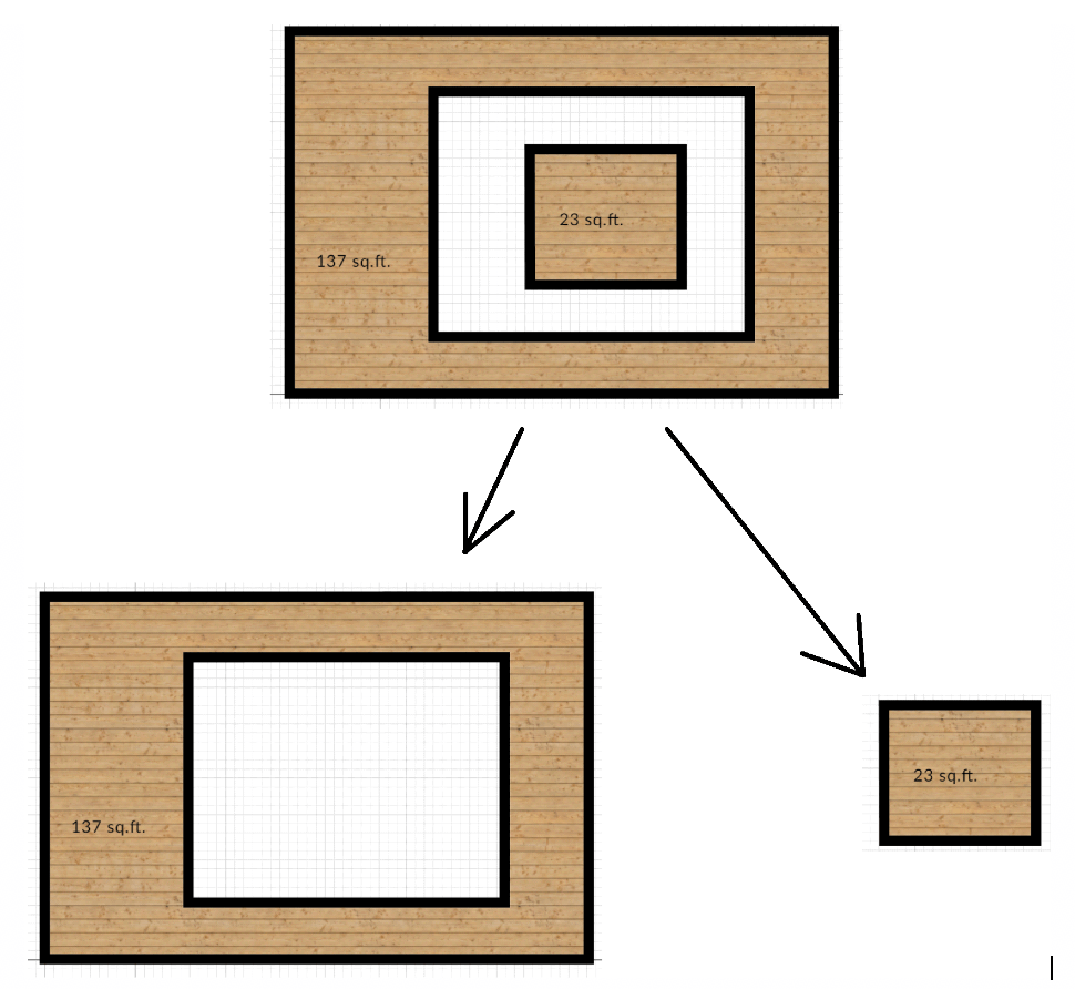
The ‘room inside a hole in a room’ will be stored as one boundary for the outer, larger room (with a large hole inside) and another boundary for the inside room (with a smaller hole). Boundaries are not connected to their composing walls in any way. The position and center of the boundaries are calculated runtime based on their height, their level’s base height and the height attribute when necessary.
Label holds the name of the room, position is a point inside the polygon (so Space Designer’s boundary manager will know which boundary this information belongs to).
SpaceModel
{
  "uid": string,
  "level": string,
  "name": string,
  "entityUids": string[]
}
Space Designer Blocks are exported as SpaceModels with the usual uid, level, name parameters and an entityUids array that contains the unique identifier of every other entity that is part of given space. Rooms themselves are represented as BoundaryModels (see above), so only blocks will become separate spaces.
ProjectModel
{
  "projectName": string,
  "storeys": StoreyModel[],
  "spaces": SpaceModel[],
  "entities": EntityModel[]
}
The root object of the SDCF JSON represents the whole project. It stores the project name, and storeys as an array of StoreyModels, spaces as an array of SpaceModels, entities as an array of EntityModels.
The SDCF JSON uses the following coordinate system:
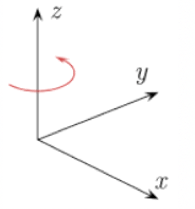
(Both Space Designer Core and SDCF uses a Z-up cartesian coordinate system. Space Designer entities store their own coordinates right-handed, but the SDCF specification uses a left-handed system, so upon SDCF export, the y-coordinates are flipped.)
The unit of measurement everywhere in the SDCF JSON is centimeters.
We are developing a converter to create industry standard IFC files from SDCF input.
In the exported IFC file:
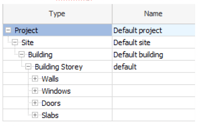
Project
   └─ Site
        └─ Building
             ├─ Building storey (Level in Space Designer)
             │    ├─ Spaces
             │    │    ├─ Space (Block in Space Designer)
             │    │    │    ├─ Curved walls
             │    │    │    │    ├─ Wall segment
             │    │    │    │    ├─ Wall segment
             │    │    │    │    └─ ...
             │    │    │    ├─ Walls
             │    │    │    │    ├─ Wall
             │    │    │    │    ├─ Wall
             │    │    │    │    └─ ...
             │    │    │    ├─ Items (Doors, Windows, etc.)
             │    │    │    │    ├─ Item
             │    │    │    │    ├─ Item
             │    │    │    │    └─ ...
             │    │    └─ Space
             │    │         └─ ...
             │    ├─ Curved walls
             │    │    └─ ...
             │    ├─ Walls
             │    └─ ...
             │    └─ Items
             └─ Building storey
                  └─ ...
The format specification and the IFC exporter is under development, more documentation will follow about the possibilities and usage. For further information, contact [email protected]
